LED Sign Board
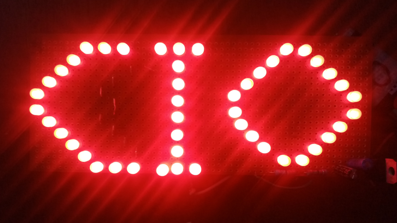
This is an easy project for anyone interested in getting into electronics as it does not contain any complex circuitry or programming.
In this project write-up, I will show you an overview of the steps I used in building the final circuit right from the planning phase to the end of the build.
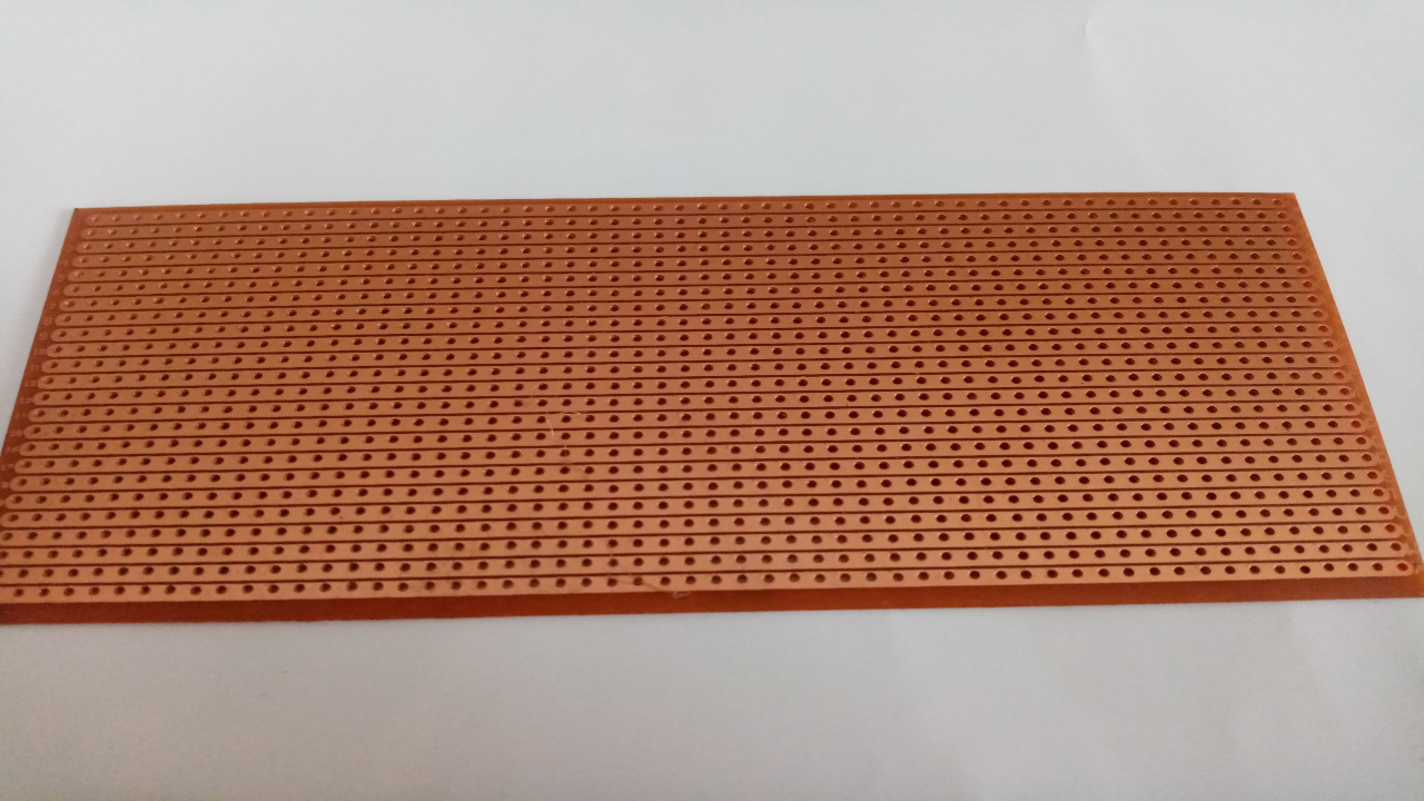
Veroboard

LEDs

Resistors

Soldering Iron
Solder Wire

USB Cable
- Veroboard / Perfboard / Prototype-board - Stripped
- As much LEDs as you need, 47 in my case NB:> One-Color LED
- Resistors (Depends on the number of LEDs; I will explain this)
- Solder Wire
- Soldering Iron
- Micro-USB Cable; The cable used to charge smart phones
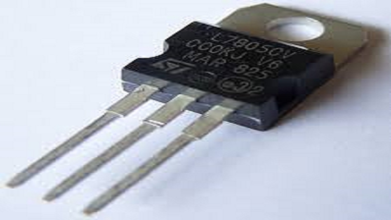
LM7805

2 Capacitors
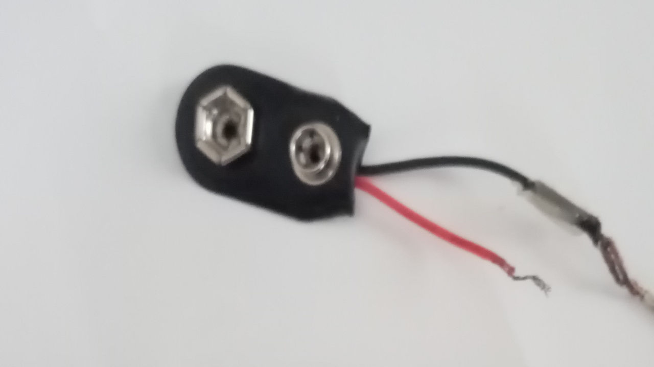
9V Battery Connector
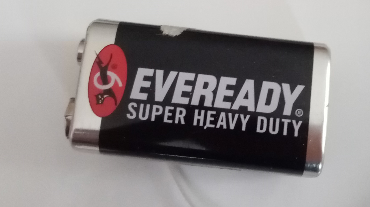
9V Battery
- LM7805 Voltage Regulator
- 2 Capacitors (1uF and 10uF)
- 9V battery Connector
- 9V Battery
This brings the total cost to approximately Kshs.120 ($1.13); Excluding the Soldering Iron and optional Components
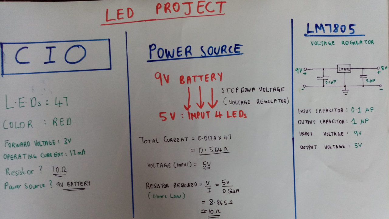
Overall Plan :> Includes Optional Components
I intend to display the Initial CIO (Chief Information Officer). More about a CIO’s role here.
Laying Down the LEDs on the veroboard,I get that I need 47 LEDs to "neatly" display the initial, CIO. You can display whatever you want, be it your name, initials or even simple characters such as a smiley face emoji
All the LEDs will be connected in parallel as this configuration allows us to use a constant voltage source (such as a standard mobile phone charger)
A typical Red LED requires 10mA of Current to work, therefore, my configuration of 47 LEDs will drain approximately 470mA of Current.(We shouldn't worry about this as most mobile phone chargers can handle 100 or more LEDs!!)
Since we will be using a 5V Power Source, we can use Ohm’s Law to get the Resistors we would need
$$V = IR$$
$$R = V / I$$
$$R = 5 / 0.47 = 10.638Ω$$
I do not have a 10.638Ω resistor! But I have 22 Ohm Resistors. I can connect two of these in parallel to get 11Ω (close enough to 10.638Ω)
Now it’s time to build the Project!
It is useful to mark the Veroboard with a marker so that you have a reference while placing your LEDs, before soldering them permanently in place.
Depite the Fact that I have been soldering for a while now, I still take precautions when working with tools such as the Soldering Iron!
All that’s Left after soldering all the LEDs is ensuring all the positive terminals of your LEDs are connected together and that all the negative terminals of your LEDs are connected together. You should end up with one Negative and one Postive terminal to connect your power source.
It does not matter whether you connect your resistors in the positive or in the negative end (Resistors don't have polarity) but I almost always connect my resistors in the positive terminal.
To be honest, my soldering job got messed up and eventually the project looked messy and complex. But on the positive side, this is part of the learning process.
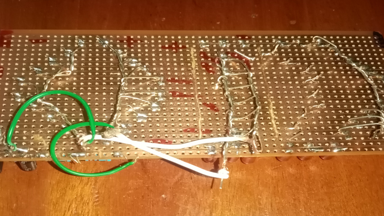
Solder Job
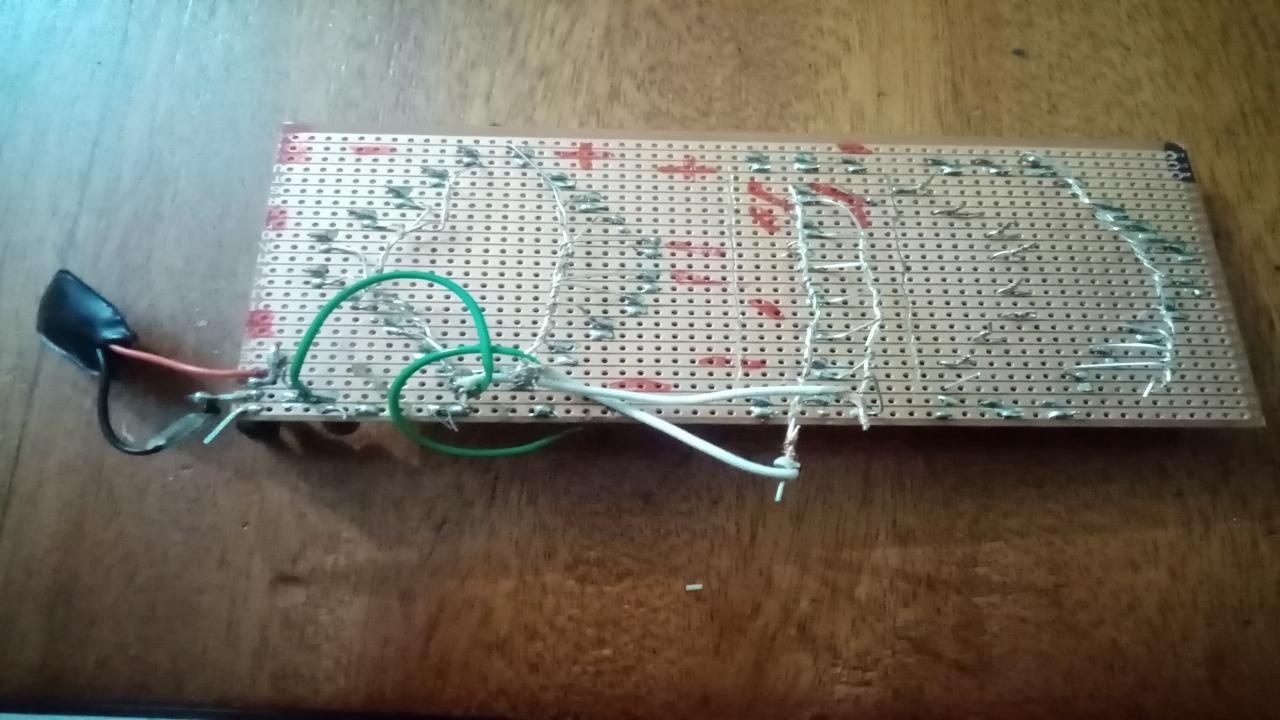
Solder-Wire finished!
Connect the positive end of the USB cable to the positive terminal and the negative end of the USB cable to the negative terminal.
Plug the cable to the adapter and Enjoy. (A 9V Battery in my case)
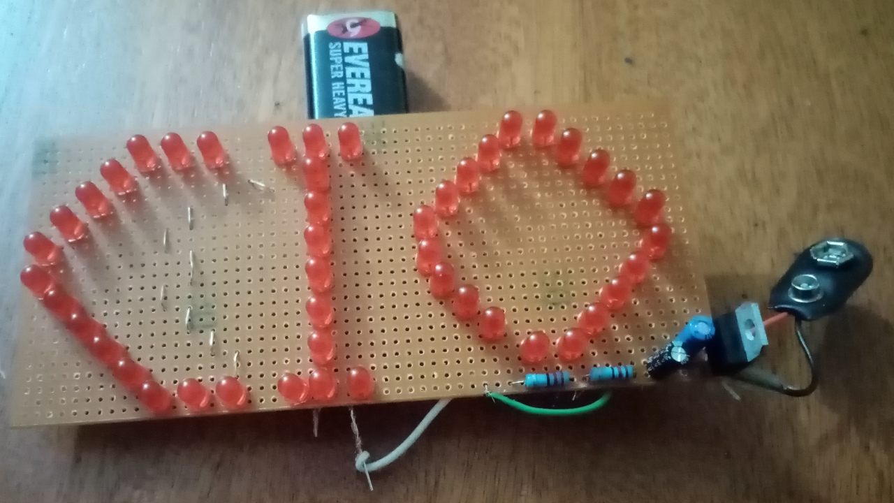
Final Product
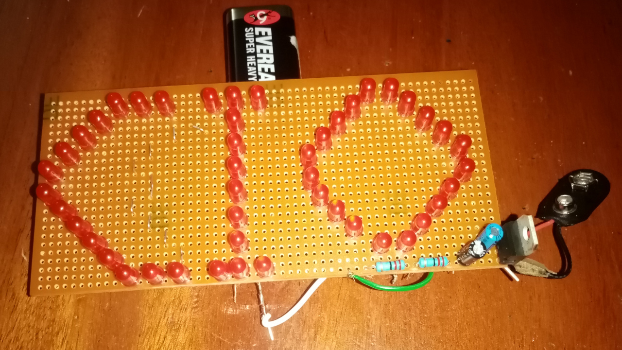
Lights Off

Lights On
Looking for something more future-proof and versatile?? Let's build the optional Circuit!!
This part of the tutorial covers the use of a bit more complex circuit :> We will be adding a voltage regulator to our project so that we could use a more flexible power source option The circuit we will be building looks like this:
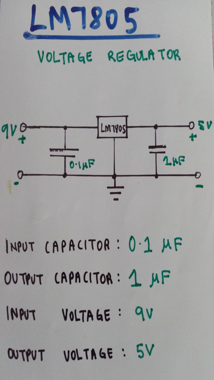
The Circuit to Build
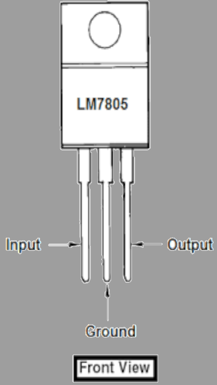
LM7805 Pinout

What it Does
The 1uF capacitor is connected to the input of the LM7805 while the 10uF capacitor is connected to the output. The capacitors ‘’smoothen’’ the power and basically makes the circuit more efficient.
With that done, I used a 9V battery to power the circuit. For your options, you can use any power source as long as the voltage is above 7V and less than 24V DC
DO NOT USE AC WITH THIS PROJECT UNLESS YOU HAVE A SUITABLE ADAPTER. I AM NOT LIABLE FOR ANY DAMAGES OR INJURIES CAUSED IN THE MAKING OR USE OF THIS PROJECT!!!
For any Questions or Comments, Feel free to Contact Me.